Am I completely fucked or is this fixable?

3 years ago by dysprosium to c/ece

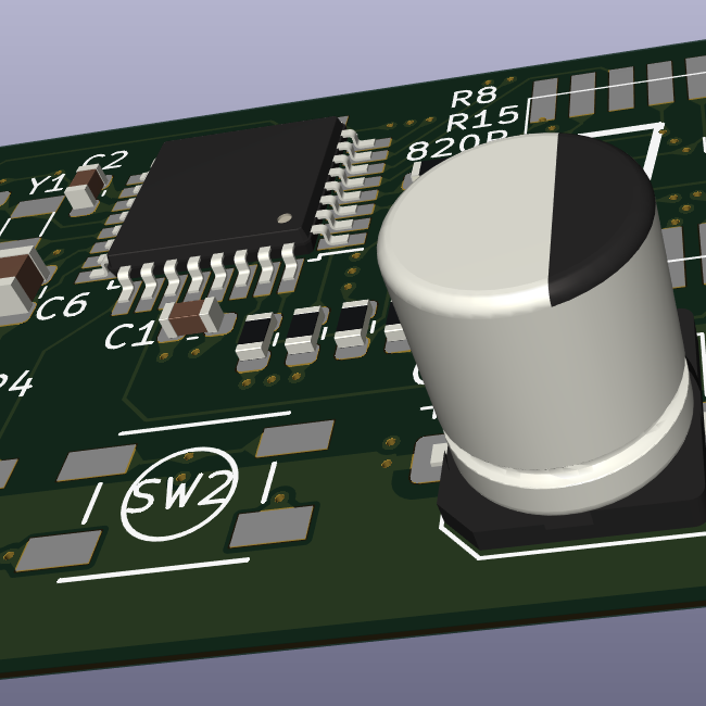
I don't care what's it gonna take. I just want a connection. I guess I can connect the VCC to another voltage source, but I have the same thing happened to TX on another circuit board, although that one can "flip" (it is still attached marginally... at one end).

Board: T Deck Lilygo.
stingpie 31 points 3 years ago

Usually you can scrape off the solder mask to expose the copper layer, then use a bodge wire to connect the trace to the connector.

path: 0 9207146, hotness: undefined, score: 31, children: 8
InevitableWaffles 6 points 3 years ago

This is mostly likely the best solution. There are land repair kits but it does take a lot of finesse to get those right.

path: 0 9207146 9207433, hotness: undefined, score: 6, children: 7
dysprosium 2 points 3 years ago path: 0 9207146 9207433 9208782, hotness: undefined, score: 2, children: 6
InevitableWaffles 1 point 3 years ago

If you know where that chip goes, you could bodge straight to it as well. 3V should be fine. I would imagine tx Rx would be point to point as well. Someone correct me if I'm wrong.

path: 0 9207146 9207433 9208782 9209265, hotness: undefined, score: 1, children: 0
InevitableWaffles 1 point 3 years ago

Looks like that goes to a via. Could scrape the solder resist back there and bodge straight in rather than try and hook up to the trace.

path: 0 9207146 9207433 9208782 9209240, hotness: undefined, score: 1, children: 4
dysprosium 1 point 3 years ago

goes to a "via"? Meaning it's not directly to the ESP? Is the schematic I provided not what it seems?

rather than try and hook up to the trace.

well I never said I'd hook it up to the trace, right? Or am I misunderstanding?

path: 0 9207146 9207433 9208782 9209240 9209496, hotness: undefined, score: 1, children: 3
Thorry84 6 points 3 years ago

Find another good place this goes to and do a bodge wire.

I think (but you'd have to check) RX/TX connect directly to the ESP board, so that's an easy place to put in a bodge wire to.

VCC probably goes to the switch on the side? That would be easy to bodge to as well.

path: 0 9207413, hotness: undefined, score: 6, children: 4
dysprosium 1 point 3 years ago path: 0 9207413 9208583, hotness: undefined, score: 1, children: 3
Thorry84 1 point 3 years ago

Yes it's as simple as that. I would recommend checking with a multimeter to be sure of the connections.

Simply run a wire from the connector to the right pin on the ESP board. You can solder to the side to make it easier.

One thing to look out for is sometimes schematics mention the ESP pin and sometimes they mention the ESP board pin, which is different. That's why it's a good idea to double check you have the right pin. You can check out the ESP datasheet to check which pins are TX and RX and use a multimeter to beep it all out. Once you know you've got it right, solder a little bodge wire and it's all fixed.

path: 0 9207413 9208583 9208731, hotness: undefined, score: 1, children: 2
dysprosium 1 point 3 years ago

checking continuity with multimeter is a bit hard since the pad is butchered, but I guess I can use the other board to check this pad's path to the ESP

path: 0 9207413 9208583 9208731 9208995, hotness: undefined, score: 1, children: 0
dysprosium 1 point 3 years ago

nicenicenice. Thanks a lot. I am not doomed after all

path: 0 9207413 9208583 9208731 9208973, hotness: undefined, score: 1, children: 0
Treczoks 2 points 3 years ago

Should be easy. When you follow the lost pads' trace, it goes through a through-hole just above the RTX pad. Scratch it free, solder a small wire in there (verify that you've got contact!), then solder the connector onto the remaining pads and solder the wire to the VCC pin of the connector.

Pro tip: Don't yank on the cables!

path: 0 9223831, hotness: undefined, score: 2, children: 1
dysprosium 1 point 3 years ago

I yanked a connector that I wanted to remove. I don't have needle thin nippers/pincers, and when I held my iron against the pads nothing happened. Am I missing something?

I guess a good set of nippers, but idk man...

path: 0 9223831 9233655, hotness: undefined, score: 1, children: 0
remotelove 1 point 3 years ago

I just fixed a similar problem while I was replacing an SMD cap. Same solution as the rest of the comments: Solder and a small wire. (It was just a larger decoupling cap anyways.)

Actually, I expanded on that in an extreme way with more solder and more wire to fix the joints on a barrel jack that was breaking off on the same board from above. My point is that brute force repairs are OK, even if it looks like shit. A simple repair can go a very long way, actually.

path: 0 9482094, hotness: undefined, score: 1, children: 0
ece
ece

@lemmy.world

login for more options
3134
104
27

Electrical and computer engineering (ECE) community, for professionals and learners. Discuss ECE related topics here, for instance digital design, signal processing, circuit analysis, electromagnetics, microelectronics, power electronics, RF electronics, etc.

go to feed...