3
40
Susan_B_Good

@discuss.tchncs.de

Susan_B_Good 6 points 3 years ago

If you mean a replacement slide-in US standard module - I fear that your chances are slim. I don't know of a standard that applies to such plates. As it came with a, presumably, external disc drive - asking that manufacturer or its US agent/distributor for help might get something. Even a free replacement power supply. Worth asking, surely?

I don't recommend using an inline adapter - unless used vertically, the leverage would be too great, unless you added a third leg.. You might look for a right angle adapter - that's the norm in the UK. They can work out well.

Otherwise, you could get an EU socket strip, replacing the plug on the end of its cable with a US one (if it doesn't actually come with a US plug already).
path: 0 513631, hotness: undefined, score: 6, children: 1
Susan_B_Good 5 points 3 years ago

Usual situation - if I needed to interface to 5 cameras I wouldn't start with ones that needed: "The DVP physical interface consists of a single, 100-conductor, 110-ohm cable organized. as 45 differential signal pairs. These signal pairs consist of the following: • 36 RGB data pairs. • 2 clock pairs." So, you would be interfacing to 5 x 45 differential pairs. I'd be looking for camera modules with serial output....

Or, as you suggest, give each camera something that can convert that lot into a single serial data stream. Or even process it down to a QR code and just send that. Or even do what-ever it is that you want to do with that code, once received.

path: 0 683221, hotness: undefined, score: 5, children: 2
Susan_B_Good 5 points 3 years ago

The standard countryside yokel reply when asked for directions applies, " Arrh, If you need to get to there, I wouldn't be starting from here".

For battery powered LED lighting - you shouldn't be using 12v LED strips. You should be using bare LEDs and a constant current supply. Converting cell voltage to 12v, only to use (probably) resistors to limit LED current isn't the way to go.

You will lose far more, efficiency wise, starting from there, than you are worrying about losing in the series or parallel considerations.

But then, you'd design the required power source and then the charger associated with it - not start with a charger, which then constrains your battery pack topology.

path: 0 466627, hotness: undefined, score: 5, children: 0
Susan_B_Good 4 points 3 years ago

Solder has very strong surface tension forces, when very fluid. So, if there is lots of flux gel present between the pads, and the bridge is broken only momentarily, the solder will draw back to create the minimum surface area on each of the pads. It's almost unbelievable to see, when it happens.

Almost all of my small workshop hand tools are stainless steel medical ones - the local Government Surplus Depot sold off warship's "First Lieutenant's Surgery Kit" and I bought one. Then went and got another one. They have this scraper tool that just needs to be drawn across the solder bridge and the solder snaps back to the pads.

It does need the area to be flooded with zero residue flux, though. Which both helps the solder to be really, really runny and follows the tool, so that the gaps are filled with flux.

path: 0 98861, hotness: undefined, score: 4, children: 2
Susan_B_Good 4 points 3 years ago

On a KISS basis - I tend to just use a bimetallic switch or omit the temperature control and just run the fan from power up. It's possible for a processor to suffer some non-handled exception where it no longer executes the temperature management routine.

path: 0 1115367, hotness: undefined, score: 4, children: 0
Susan_B_Good 4 points 3 years ago

What worked for me, that may not do so for anyone else - is to take an existing circuit (usually a reference one provided by a manufacturer) and build that. Get that working (sometimes, it hasn't worked- the manufacturer's technical support department has often been very helpful, especially when their reference design has a design fault or has been misprinted - after doing that, they used to send me unmarked, pre-production chips/etc to play with and provide feedback).

Then modified that design, to test my understanding. Tried different board layouts, guard rings, etc and documented the effect. When it didn't work as expected - took that back to their tech support to see if we could work out why.

So, for me, taking something that works and keep modifying it, just a little.

path: 0 647441 663244 666351, hotness: undefined, score: 4, children: 0
Susan_B_Good 4 points 3 years ago

I'd suggest peeling off just one strand of the wire and use that. You will need to insulate the wire from the nail - Wrapping paper around the nail will do. You will need to insulate the wire from itself, so that adjacent turns don't touch. You can just space the turns out along the paper sleeve. That should do the trick. If you have twine, you can wind that on with the copper wire and use the twine to keep the turns from touching each other.

Oh to straighten copper wire, if you don't know this trick - hold your nail in a vice and wrap a single turn of copper wire around it. If you then pull on one end of the wire, keeping a little tension on the other - with a bit of practice it will give you a very straight end result, as the wire pulls away from the nail.

path: 0 999688, hotness: undefined, score: 4, children: 0
Susan_B_Good 4 points 3 years ago

Just a word of caution - education is a process of diminishing deception. Books provide a simplified version of real World electronics. Universities and colleges put a lot of effort into designing lab practicals that will actually work and give the predictable results that students expect.

So the normal learning process when it comes to op amps - is to read and understand the theory. Then complete those crafted lab practical exercises - having been introduced to the added complication of systemic and random errors. Then do your own thing, when all the remaining Real Life complications hit you like a brick.

So, if you can find a course in analogue electronics, even a distance learning one, you might find the steps are smaller and more easy to assimilate.

path: 0 647441, hotness: undefined, score: 4, children: 2
Susan_B_Good 4 points 3 years ago

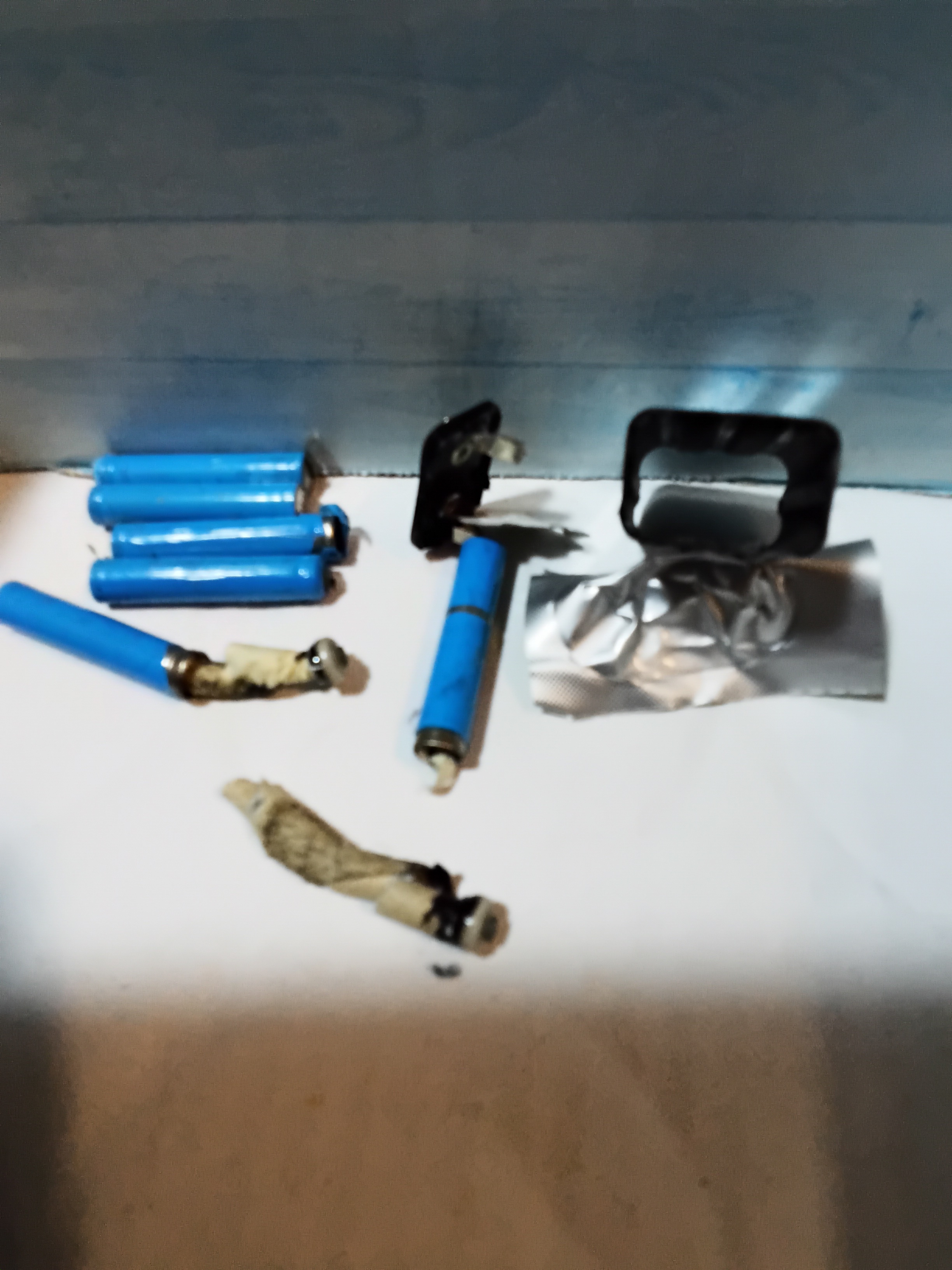
Found it! (complete with end cap) - contents completely removed themselves..

path: 0 637387, hotness: undefined, score: 4, children: 0
Susan_B_Good 4 points 3 years ago

That is pretty much exactly a conventional momentary switch. It just happens to be packaged for use controlling something a little different.

It should be fine for your application.

One thing to note - the contacts will probably "bounce" as the switch is closed. Produce a string of momentary connections and disconnections for, oh, say the first few thousandths of a second. That's perfectly normal for a mechanical switch.

That won't matter in its intended application. But if you are using it with electronics, say counting the number of times the switch is operated - the results can be unexpected.

You can look up "debounce" to see how this can be worked-around.

path: 0 367232 367544 367933 368553 374675, hotness: undefined, score: 4, children: 1
Susan_B_Good 4 points 3 years ago

Wear trainers not sling backs. Molten solder and your tootsie don't go well together.
I turn the printed circuit board component side down and wave a hot air gun over the flip side, whilst tapping the board against the edge of work bench. The result is usually a cascade of components (and blobs of molten solder).

Very therapeutic. When I'm stuck trying to work out how to do something, when everything I have tried has failed miserably, I deconstruct something electronic. No, I keep well away from psychiatrists.

You (I anticipate) won't be doing this 9 hours a day, 7 days a week - most of the nasties are long term exposure ones, so a one-off should be fine. If anything ever irritates your eyes or throat, get out of there and ventilate the place.

path: 0 393778, hotness: undefined, score: 4, children: 0
Susan_B_Good 3 points 3 years ago

Acid etch, followed by electrolytic copper plate, followed by nickel plate.
Sorry, can't help with sourcing a replacement.

path: 0 534949, hotness: undefined, score: 3, children: 0
Susan_B_Good 3 points 3 years ago

Reminds me of a boat with a hot bulb inboard engine that we once had - the exhaust manifold had rotted away. Irreplaceable, the engine was very old.

My university lab mechanic offered to make a new manifold - he used a steel plate and sections of a scaffolding pole. It looked a little like the above but worked perfectly.

We sold the boat and the new owners ripped out the engine and THREW IT AWAY AS SCRAP. Put in a small diesel. Philistine.

path: 0 655576, hotness: undefined, score: 3, children: 0
Susan_B_Good 3 points 3 years ago

I suggest that you give details of the iron (and tip) and solder that you are using and a close up photo of the wires that are being problematic.

The iron temperature control may be faulty and the iron just not getting to soldering temperatures. Or you may have it set too low.

The thermal mass of typical USB wires is so low that, if the solder actually melts freely at the tip end when not soldering anything, it should do so when soldering these wires.

path: 0 1063329, hotness: undefined, score: 3, children: 0
Susan_B_Good 3 points 3 years ago

I'm puzzled - you describe wanting to add a headphone jack (eg an output jack socket into which headphones can be plugged) - yet you seem to actually want a socket that provides auxiliary input.

However, if you are indeed trying to add external input and are disconnecting the inputs to an amplifier - you might want to tie those disconnected inputs to ground.

path: 0 735229, hotness: undefined, score: 3, children: 7
Susan_B_Good 3 points 3 years ago

You probably have already sussed this - but:

DuPont connectors equates to logic level signals. There may even be a 3.3 v <>5v link selector on the adapter.

Whereas DB9 equates to "RS232" level signals. Generally, at least the capability to accept those voltage levels, even if not necessarily producing them.

My first step tends to be to connect tx to rx and see if characters typed in a terminal/emulator get echoed.

An RS232 breakout box is pretty much a given necessity, when it comes to sorting out what's happening on all those pins and sorting out what to connect to what.

path: 0 436882, hotness: undefined, score: 3, children: 0
Susan_B_Good 3 points 3 years ago

The standard way of looking at this is to consider a capacitor-resistor series combination going to ground. Connect a 10v (wrt ground) supply to the capacitor and the voltage across the resistor rises to +10v, then decays. Now connect that capacitor to ground and that same resistor gets -10v across it, which then decays. Whatever is connected to the capacitor "top" terminal has to be able to sink current as well as source it.

That's what generators in simulators do - they have zero internal impedance (usually). They sink currents as well as source them.

path: 0 974674, hotness: undefined, score: 3, children: 0
Susan_B_Good 2 points 3 years ago

You want hysteresis and an energy gap - which means putting energy into the system. You could use a latching relay to minimise insertion loss, however the loss in a conducting MOSFET can be pretty minimal.

SLAs self-discharge, of course.

If the load versus time is predictable, you could use a latching relay and delay voltage checking until the time window for potential cut-off. Or make it entirely period based and not test at all.

It may be that you never need to sense voltage, if your time period between recharging is small enough.

Many operate on that basis - the time interval between recharging may be out of their control (in our case, once, we only had mains electricity between 2am and 4 am each day..) and they provide themselves with enough battery capacity to last that time interval, with a reserve. So no low voltage cut off necessary. So no testing necessary.

path: 0 628163, hotness: undefined, score: 2, children: 0
Susan_B_Good 2 points 3 years ago

I think that it is the same stuff, just will propellant added in the aerosol. A small squeezy bottle with a needle is better if you have live stuff nearby - but you can always fill one from an aerosol

path: 0 930365 946528 950752, hotness: undefined, score: 2, children: 0
Susan_B_Good 2 points 3 years ago

You can make your own current-limited power supply, probably from bits and pieces you already have. Let's say that you have a 5v dc power supply and a hand full of rectifier diodes and resistors (various values and sizes).

Put a series chain of forward biased rectifier diodes and resistor(s) across your 6v supply. Choose enough diodes to give you a 3v output. Now choose a combination of series/parallel resistors to give you a 2v drop with a current of, say 100mA. You need 20 ohms - so that could be 5 x 100 ohm resistors in parallel.

The most current that can put out is the full 5v across 20 ohms - but at that point the output voltage will be near zero.

Bench supplies, well reasonable ones, allow you to set a current limit as well as an output voltage. At loads below that current limit - it operates as a constant voltage supply. At loads above - it operates as a "constant current" supply. You would set the output current limit to 100mA and that's the most that it will output.

Now the rectifier diodes plus resistor would allow the current to increase above 100mA, up to 250mA when the output voltage will be near zero (short circuited) - if you want better than that, then you can add a transistor and a few other components.

path: 0 374471, hotness: undefined, score: 2, children: 0

thanks for using Leebra!

go to feed...