Thanks!
Is that on oshpark?
Yes it’s there : https://oshpark.com/shared_projects/x73ewc7D

@lemmy.world
Thanks!
Is that on oshpark?
Yes it’s there : https://oshpark.com/shared_projects/x73ewc7D
2A per LEDs. Less than expected, either 2x 16A3V (8P) or 2x 8A6V (2S4P) configuration, about 50W per channel.
Edit: nevermind about the configuration, the page says boost, Hank said buck on BLF a while back, maybe a confusion or a change during development.
I’m curious how the head and tube perfectly align for the one on the right (Citadel ?), I’ve seen it before and thought it looks really great. Although I wish these nice lights were more compact, they look fairly large for the size of the cell.
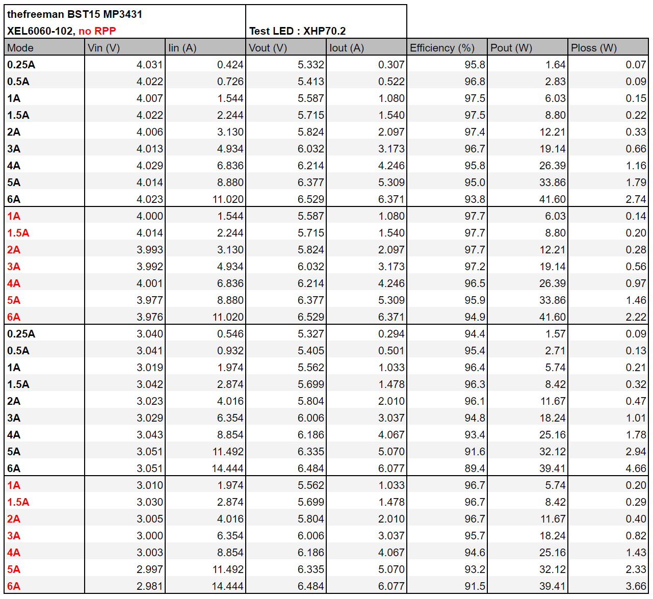
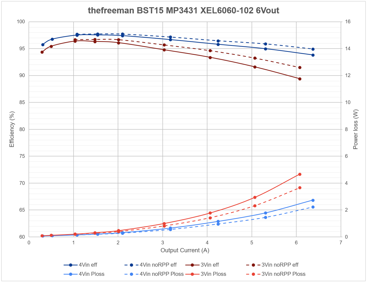
Test results for BST15 (the smol one) :
Very cool!
Nice work, thanks for the diagrams.
if you have an emisar light and can disassemble it, then you can try soldering an airwire from the sense resistor to the button LED pad (sacrificing it for that) or a free ADC pin, but that's more difficult. If that cause problems with the current regulation, add a 10k resistor or the likes.
with a linear driver Iout=Iin so it's simple, with a boost driver Iin=(Vout x Iout)/(Vin x efficiency), thankfully Vin is already bein measured, Vout and efficiency need to be guesstimated.
and the one on the left is a real monster!
Yup, it’s pretty hefty : 14.5x13.5x10.7mm
The small one dubbed BST15 is a 15mm component clearance/17mm total diameter boost driver, rated for 40W (6A6.5V, 3A~13V), with HDR (low moonlight), it’s compatible with e-switch (Anduril) and Mike_C’s OTSM implementation for clicky switch, I made it (with his blessings) so that it is easier to build than his version and added reverse polarity protection , my first version had some issues at high current, at the time I didn't do too much troubleshooting and left it aside, recently I made an updated version, which is the one I just assembled and it works well. The next step is assembling a couple more to send to Mike so that he can finish his firmware, then I’ll share the PCB/BOM for people to assemble it themsleves.
The big one is also a boost driver, 1S input, I’ll post more detail once I have finished testing it, I did some partial efficiency test already but I don’t have a power source powerfull enough to test it at max current 😅.
It’s for a rather popular light so it shouldn't be too hard guess which.
Thanks 😊
That's interesting. 3S batteries and 4S emitters?
4S wouldn't be enough for low modes, 2.5V×4=10V, while 3S cell would be 12.8V fully charged, so with boost the only viable configuration would be 8S. I wonder if it's an error since he said it was a dual buck driver on BLF.
I use Kicad.
Acebeam models use either buck or boost drivers. X50 buck, X75 boost.
Unrelated to OP but commenting here since it's about reddit. Did you notice that mentioning Lemmy on reddit gets your comment shadow removed ? here's two of mine I just noticed thanks to this AMA about Revedit
I already know someone who could machine parts for me, so yeah I should start designing something.
The aux LEDs are ON-high/ON-low/OFF and not controlled via PWM due to power consumption concerns for indicator aux LEDs that are designed to be ON all the time. With PWM the MCU has to stay awake and it would draw the cell too fast, due to that aux LED PWM control has not been implemented.
With the T1616 there might be a way to do PWM with relatively low power consumption, but that hasn't been tried yet.
Thanks
although I think these drivers could become very expensive and once the manufacturers start substituting components it’s efficiency could decrease.
The buck ICs I used are actually not very costly, the inductors are a bit pricey but since there is quite a bit of free space on the board, (and unused stuff for low side sensing because I made it both high/low side sensing) larger cheaper Chinese ones with similar specs could be used and the performance would be unaffected.
Generally that’s what I would do if contracted for a driver, for example I made my BST21 one sided and 0603 min size for easier self assembly, due to that I used a 70x0 inductor size (~7.5×7.5mm, variable height), which if it was Chinese branded would not have satisfactory specs.
If asked to design a similar driver I would use a larger 1040 inductor (10×11mm×4mm, common size used in Convoy drivers) that are even a bit better than the Bourns/Coilcraft 70x0 but cheaper, the driver would need to be double sided but produced in large quantities this doens’t have a high cost. The converter IC can’t he be substituted, the only other power component would be the RPP PFET but there are a few pretty good chinese ones like the one used in Noctigon boost drivers.
Thanks.
C'est beaucoup mieux que les autres apps que j'ai testé et surtout elle est adaptée aux tablettes, par contre les prix sont un peu élevés.
thanks for using Leebra!
go to feed...